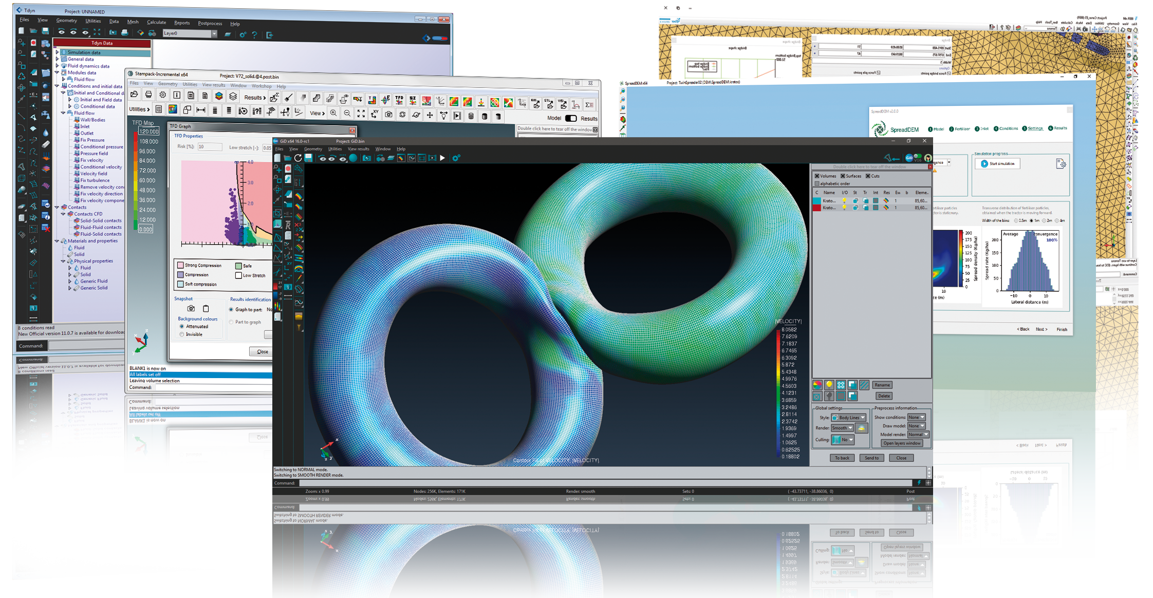
GiD 10 Frequent Asked Questions Pre and post processing system for Numerical Simulations.
International Center For
Numerical Methods In Engineering (CIMNE)
Solve problems
Solve problems
Questions about GiD setup. You can get more information in www.gidhome.com
If you are experiencing problems on saving password or preferences on windows 7 go to Control Panel->Users Accounts->Change Users Accounts Configuration (UAC)
And set it to the lower level, Not notificate never.
After that you will need to restart the computer to changes take effect.
If GiD install/.tgz does not run on latest ubuntu 8.04 perhaps you are not able to execute the installation program of GiD nor the kernel-2.6 packed (.tar.gz) version on the latest ubuntu distribution.
Check if the distribution you are using is a 64-bit one with
uname -a:
..... x86_64 ...
If you have used the Wubi installation program, by default it installs the 64-bit distribution on a machine which is able to run 64-bit applications, which are all the machines by now.
It seems that the default 64-bit installation of ubuntu (and kubuntu, xubuntu) does not include the 32-bit support to execute 32-bit applications....
When oppening the "Help -> Register GiD ...", if some USB memory stick is plugged, a "Sysinfo selection" window must be opened to ask the user which device can be registered.
in some Linux distributions (e.g. Suse 10.x) the USB device is not detected, and this "Sysinfo selection" is not opened.
This is because /proc/bus/usb is not automatically mounted, it can be manually mounted (as root user) with
GiD is a general purpose pre-postprocessor for computer analysis. All the data, geometry and mesh generation can be performed inside. Also, the visualization of all types of results can be performed. It is easy customizable and adaptable by the final user.
It can be adapted to an analysis by the creation of a 'problem type'. In this problem type, it is explained to GiD how are the boundary conditions, materials and al the information needed for the analysis. It is also shown to GiD how is the format of the input file of the analysis program.
There is a second level of adaptation where, by the means of the TCL/TK scripting language, it is possible to change the look and fell of the program and add some functionality to it (until a certain point)....
To write data from GiD to a calculations program, it is necessary to create a 'problem type' for it.
A 'problem type' is basically a collection of text files, copied inside a common directory with .gid extension. This files define your material fields, conditions, the template to write your calculation file, etc.
It is quite easy write a simple 'problem type'. The first step is to check one of the examples that are included in the GiD distribution like 'problem_type_solid1.gid'. Studying it and modifying accordingly to suit your needs you will get a GiD that can write the files that your calculations code can read. ...
It is not possible to do it inside GiD, and standard exchange formats like IGES doesn't support this 'polisurfaces'
The 'Rjump' mesher can create elements with nodes on different surfaces. User can select the lines to be jumped, then from the meshing point of view it's like a 'super-surface'
Gid have a function to create automatic 6-sided volumes (Geometry Create Volume Automatic Struct).
In the current version, several volumes can be created simultaneously, selecting all the boundary surfaces. GiD automatically detects the holes.
To add manually a hole to a volume, invoke the menu: Geometry->Create->Volume->Hole, then select the outer volume and then select the volumes of the hole.
Option Search in volume creation permits to select one surface and GiD tries to find one volume that contains this surface.
Create another line that exactly duplicates the first one. Points must be also duplicated (Typically using copy with translation 0 and with flag 'Duplicate entities' activated).
Set another layer as active
Create a contact surface selection the two lines or more at the same time (if using copy, it has the option 'Create contacts').
Possibility to extract information about boundary edges and faces
Mesh generation and data (boundary conditions, materials, etc)>Possibility to extract information about boundary edges and faces
If you need the boundary edges or the faces of surface elements or volume elements you can do it in several ways:
Give a mesh criteria of type "mesh" to the lines or surfaces that are the boundaries of your surface or body. After generation, you will have linear or triangle or quadrilateral elements apart from the main ones.
Assign a condition "over face elems" to the line or surface that is the boundary. You can then list the element faces with this condition in the '.bas' file with the order *globalnodes or *localnodes....
Allow geometric information to be incorporated into the customization files
Do you have any plans to allow geometric information to be incorporated into the customization files, so that mesh optimisation can be coupled to the solver?
There is now one feature in GiD (field #FUNC# in conditions definition) that allows to write the number of every geometric entity for every element in the mesh. Then, you can get the geometry with any command like write ASCII or whit the order *tcl inside the bas file, and you have the relationship.
To do remeshing, it is available to read a background mesh file (of triangles or tetrahedras), containing the description of the new mesh sizes desired....
Possibility to mesh complex structured volumes using GiD
Can GiD mesh complex structured volumes?
Structured meshes can be done with complex surfaces but not with complex volumes (they can only have 6 faces or surfaces). Probably, in the near future we will add the same capabilities to the volumes that we have now for the surfaces.
The most powerful part of GiD for CFD analysis is the tetrahedra mesh generation. It permits to concentrate elements near the object of study (ship, plane or any other), and let them grow fast or slow.
Possibility to mesh complex structured volumes using GiD
The easiest meshing is defining a global size and small elements
for features are automatically calculated.
User can define a cordal error (geometry - mesh error)
User can manually define sizes over geometrical entities. This
sizes can be automatically corrected to allow meshing checking Preferences->Meshing->Automatic correct sizes.
The transition between sizes is controlled by a factor that the
user can define (Preferences->Meshing->Size transition).
I assign X condition on some nodes and then assign Y condition on some nodes(include some nodes I select when assign X condition),then I write a calculate file,those nodes I select both when I assign X condition and Y condition only have Y condition value,but the X condition is lost.Could you tell me the reason?
Response:
If you desire to apply a same condition (same name with different values) more of one times to a entity,
this condition must be declared as CANREPEAT: yes in the *.cnd file.
If CANREPEAT: no (default), then the second same condition replaces the first:...
GiD reads several files with postprocess info in a GiD-defined format.
As the information is really in a very easy format, your code (or one interface program), should write the results of your analysis in GiD postprocessing format. It is very easy to do it. Some people have modified their code for GiD in 2-3 hours. The GiD postprocessing format is defined in the reference manual and in the interactive help.
We also provide source code of the 'gidpost' library, to be linked to your C/C++/FORTRAN program, in order to write posprocess results files (ASCII and compressed binary)...
With version 6 or newer it is possible to visualize results in Gauss points, both in automatically calculated and introduced by the user.
Gauss points are several points inside every element, that are used to perform the integration quadrature necessary for the FEM. For this reason, the main variable of the problem is obtained in the nodes and the variables that need an integration of this, are obtained in these Gauss Points.
Current version can already read and display data in the Gauss points. The standard possibilities are:...
I read the postprocess mesh with mesh read. Is it correct?
Instead of using "meshread", you shoud probably input inside the postprocessor two files:
For the mesh, use: test.flavia.msh (old formats as test.flavia.bon or test.flavia.dat are unrecommended)
For the results use: test.flavia.res
Check the manual for the sintaxis format.
If the mesh is already in the preprocess, it is necessary only the results file. It must have the name MODEL.flavia.res and be inside the directory MODEL.gid In this case, when going to postprocess this file is automatically read....
Procedure to visualise a 3D velocity field with streamlines
Could you provide me with a simple procedure to visualise a 3D velocity field with streamlines?
The easiest way to define a stream line in a 3D mesh is to select a point by giving its coordinates. The stream line that goes through this point is drawn. In the contextual menu there are other ways to select several points at once. Tipically, a cut is made in the middle of the volume mesh and the points are selected in the cut.
Procedure to visualise a 3D velocity field with streamlines
How to export the mesh and the boundary conditions, materials and so on
It is possible to export the mesh and the boundary conditions just by
pressing one button (Files->Export->Write ascii). The problem is the
output format. Every calculations program has its own input format and
GiD is not prepared to know all these formats. The solution is one of:
Output from GiD in one format and make external conversion to
another one.
Define or modify one GiD 'problemtype' to suit your needs. In
this way, GiD will know what information should the user enter
(boundary conditions, materials, ...), and GiD would write the
calculations file in the exact format you need. We include several
examples of problemtypes with the GiD instalation, to help people to
develop their owns....
Yes, It can work with either finite differences, finite elements, finite volumes, meshless methods and others. In fact, as GiD only deals with the geometric and mesh part, it does not mind the type of analysis that will be made as long as it needs a mesh.
How to print in the calc file the number of the layer which an element belongs to
How I could print in the calc file the number of the layer which an element belongs to?
Now, it is available inside the bas file the layer information: *ElemsLayerNum *NodesLayerNum, *Loop Layers, *LayerNum, *LayerName, *LayerColorRGB, etc
In old versions, the layers information cannot be directly dumped into the output file. Tipicallly, it is necessary to assign a material or a condition to the elements that reflects this property. There are bassically two options:
User assigns a condition or material to the elements with a field that reflects the property that you are working with....
GiD works in any standard PC. Normally, the critical issue is the RAM memory. It must be related to the size of the mesh to be generated. As a rule about 1GB by million of elements.
An spaceball can be interesting to easily rotate and move the view.
How to make GiD x32 use more than 2GB on Windows XP or Vista
This only works for Microsoft Windows XP or Vista, and for GiD x32 version 7.5.x and newer.
In a standard Microsoft Windows machine, each program only can work with 2GBytes of memory, although there is more installed. So if you have a machine with lots of memory, more than 2GB, and running Windows XP, you can enable your system so that a program, if it is able to, sees and uses more than this 2GB of memory. In a Microsoft Windows XP 32bit environment, the program will be able to use upto 3GB of memory, and on a 64bit environment, up to 4GBytes, althought the program is 32bit.
In Windows systems, GiD can be accelerated by any 3D graphics card that supports OpenGL. The WinFast or the RivaTNT card are fast and works correctly. It has some minor bugs about incorrect visualizations.
There is no 3D acceleration in Linux by now. We are working on this and there will be in the very close future.
In Silicon Graphics all the acceleration of their cards is used by GiD.
There is a feature to disconnect the hardware acceleration of a graphics card that is not working properly. Check the 'GiD safe mode' option in the MS Windows start menu....
with cuaX as the serial port where the SpaceBall is attached. And be
sure that this cuaX serial port has READ/WRITE permisions for all the
people ( User/Group/Others).
GiD is licensed per one machine and platform basis. This means that every machine should have its own license and that if one machine has both, linux and Windows, two licenses are required. For every machine there can be as many users as desired using the program at the same time.
USB licence:
The licence is attached to an USB memory stick device. GiD client can run in the machine where this device is currently plugged.